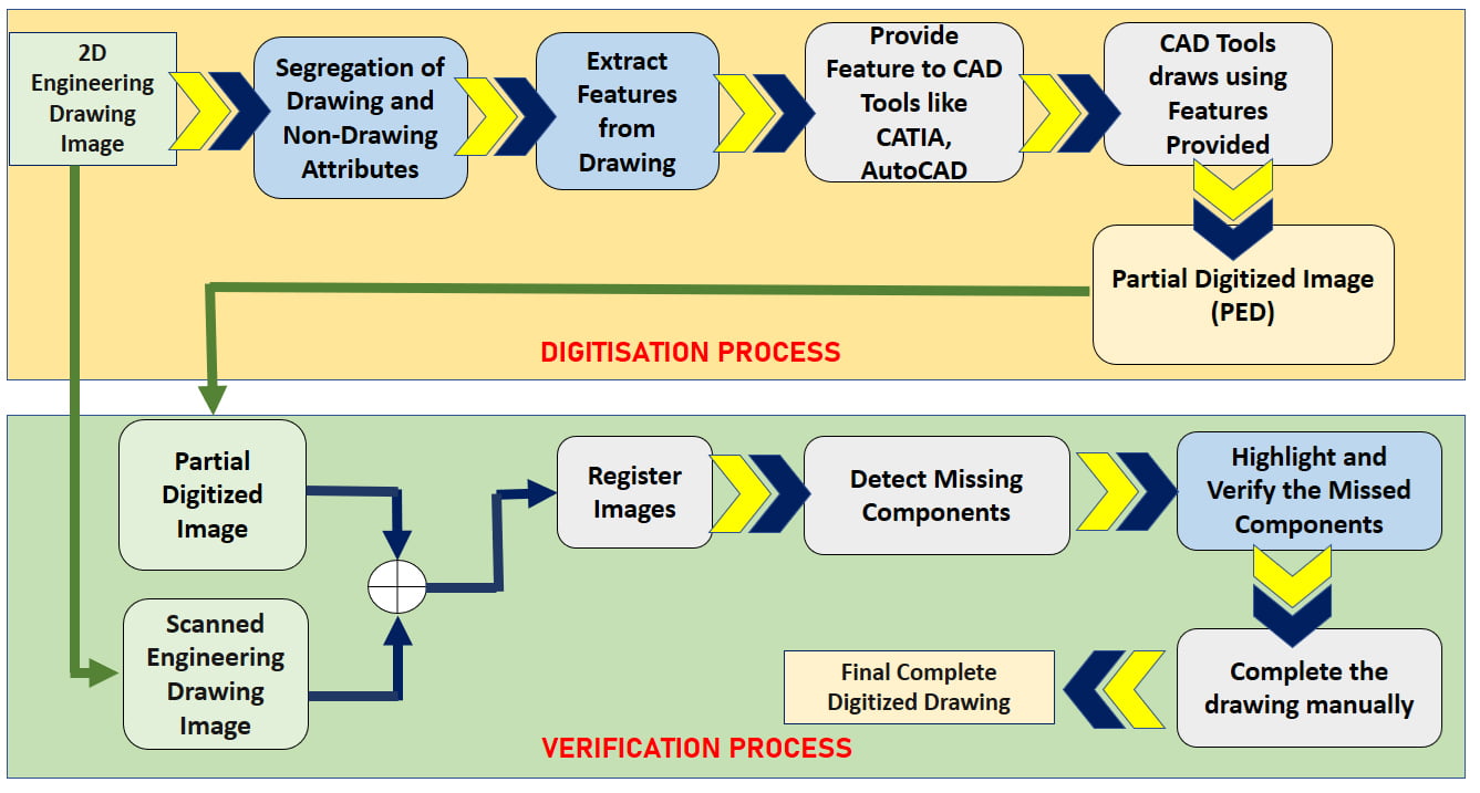
Fig 3: Flow chart of the Solution
Engineering drawings typically can contain several views of the same component, and some additional scratch views can be added for a further understanding. The information specified in the drawing are mostly which could help in recreating these in digital format. Some other relevant information such as the dimensions, tolerances are usually only specified in one place on the drawing, for avoiding redundancy and the possibility of inconsistencies. Suitable tolerances are incorporated for critical dimensions to allow the component to be manufactured and functional.
Subsequently, a more detailed production drawing may be produced based on the information given in an engineering drawing. These drawings also have an information box or title block containing details of who drew it, who approved it, unit of dimensions, projection information, the title of the drawing and the component name, etc.
The primary objective in this step is to extract entities in the form of text, information box /tables, frame information and dimensions set which is so considered to be non-drawing part/region. The non-drawing entities are also significant from another point of view. The dimension set mostly consist of arrow heads, guidelines and extension lines. The dimension set are not necessarily required to be present in all drawings (mostly Mechanical Component Drawings). The text information is mostly available in tables, outside frame region and as dimension text and Instrument tagging in few scenarios. The dimension text contains geometrical information of drawings which represents length, radius, etc. These are also preserved separately for further validation purpose. The different components of 2D Engineering Drawing is descripted in Fig 4 (a).
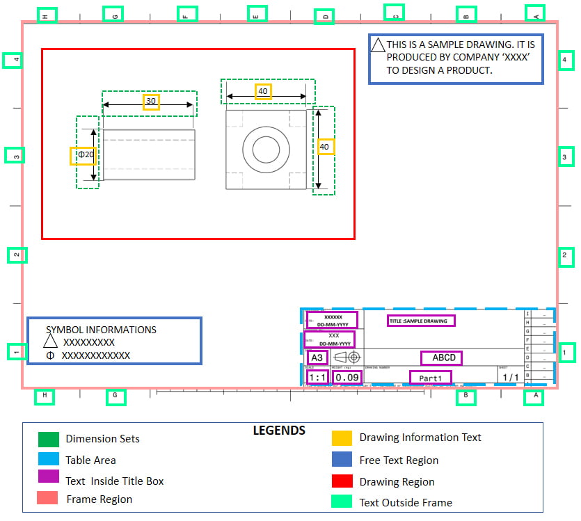
Fig 4 (a): Different sections of a 2D Engineering Drawing of Mechanical Component.
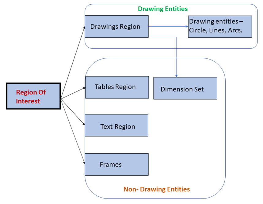
Fig 4 (b): Content of 2D Engineering Drawings

Fig 4 (c): Information Containing in a Title Box.
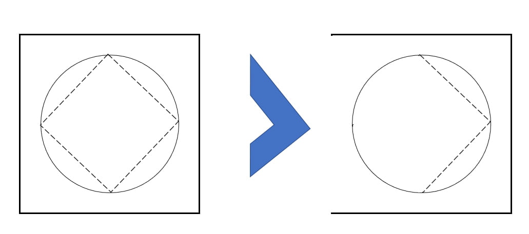
Fig 5 :Conversion of 2D Engineering to Drawing Image (left) to Partial Digitized Image (right) using AI-assist Digitization Tool. .
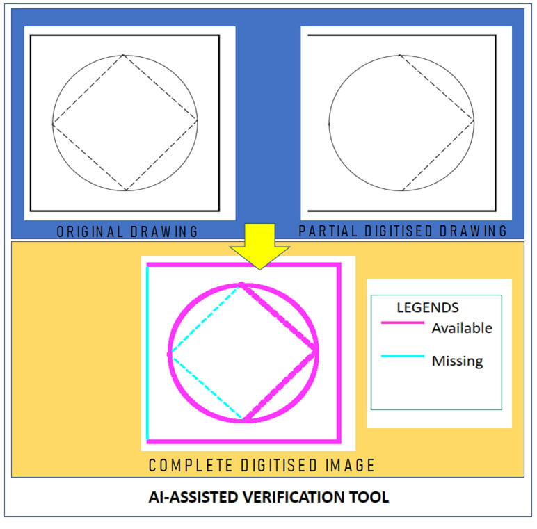
Fig 6: Illustration of AI-assistance Verification Tool.
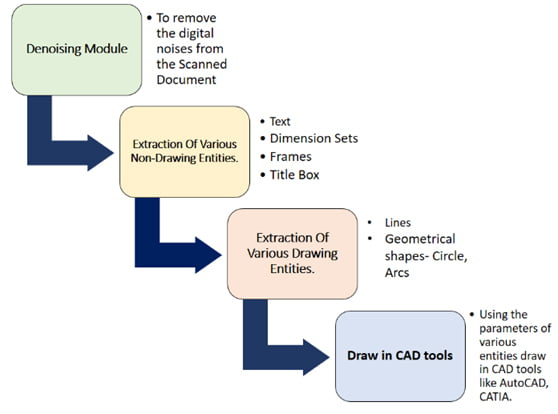
Fig 7(a): Different algorithms of “Extract Feature Module
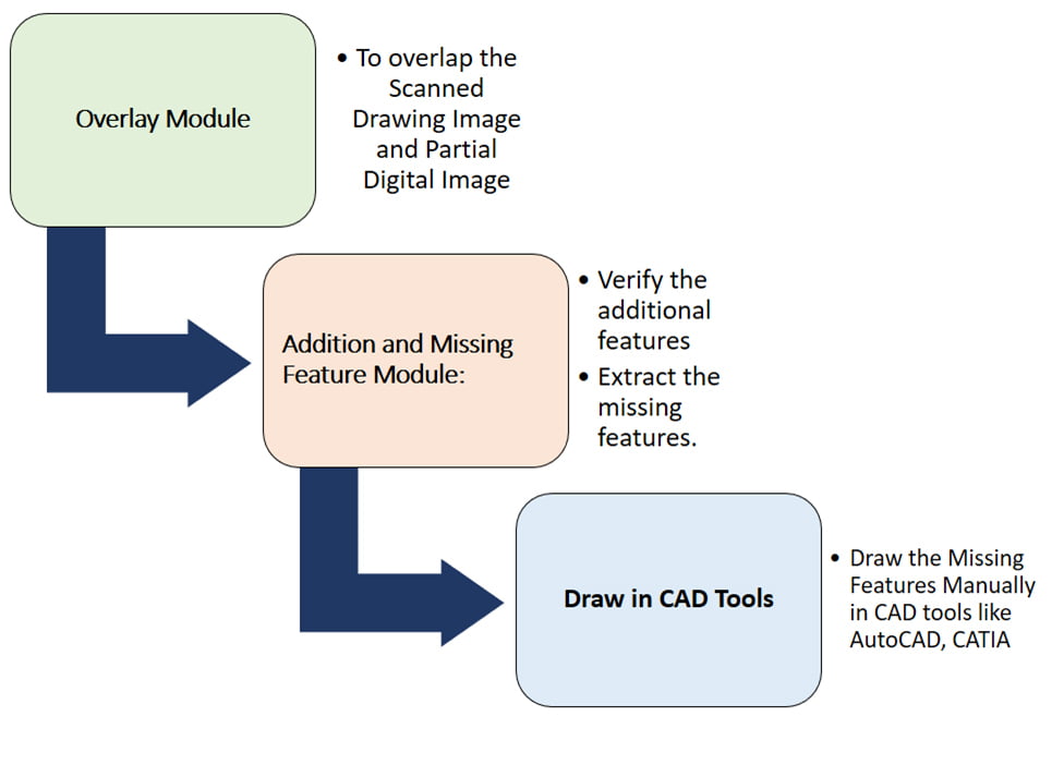
Fig7(b): Different algorithms of “Verification process